|
|
|
LED /OLED Characterization
System:
We provide system solution to
characterize the optical flux (lumen), brightness, spectral distribution,
dominant wave length, peak wavelength, and color coordination of LED/OLED.
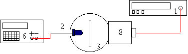
1. LED/OLED optical flux (Lumen) characterization schematic:
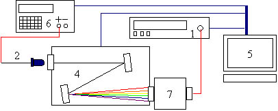
Power supply lights up the LED device, the emitted optical flux is collected by the integrating sphere then detected and read by the V(λ) detector and current meter respectively. 2. LED/OLED spectral distribution, color coordination, dominant wave length, and peak wave length analysis schematic:
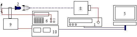
Computer controlled power supply lights up the LED device and emitted light is guided into the monochromator. The spectral components are separated by monochromator and detected by the silicon detector. The spectral amplitude is read by current meter and then stored and processed by personal computer to show the spectral distribution, color coordination, and color temperature. 3. LED angular / spatial intensity distribution analysis schematic:
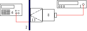
After lighting up the LED device, computer drives LED device to rotate in vertical and horizontal direction. The spatial intensity amplitude detected by V(λ) detector is then read by current meter. Computer collects and processes data from current meter then displays the spatial intensity distribution of the LED device. 4. OLED brightness (Nit) characterization schematic:
After lighting up the OLED device, a pin hole fixture is mounted in front of the V(λ) detector, the brightness (nit, CD/m2 ) of OLED can be then read by current meter.
........Back to Product
|